Latching solenoids

RECOMMENDED FOR
locking

LOCKING

shutter-icon

SHUTTER

sorting icon
SORTING
FLUID CONTROL

Product Introduction

Takano Latching Solenoids are self-holding linear actuators that use magnetic force to hold position and move axially by electrical pulse. They are energy-efficient with low heat and come in bi-stable or mono-stable types.
  • DC-powered pull-in; holds position with permanent magnet after coil is de-energized.
  • Holds position with permanent magnets—no power or locking needed, avoiding coil heating.
  • Cost efficient
Latching solenoids family

Series List

Bi-Stable Latching Solenoids TSB Series

My Image
Dimension(mm)
16 × 16 × 35.7

DC resistance

10 Ω

Holding force
3N or more
(de-energized)
Attractive force
3N
Stroke
5 mm
My Image
Dimension(mm)

20 × 20 × 30

DC resistance

7.5 Ω

Holding force

5N or more
(de-energized)

Attractive force

5N

Stroke
5 mm
My Image
Dimension(mm)

25 × 25 × 45

DC resistance

20 Ω

Holding force

15N or more
(de-energized)

Attractive force

7N

Stroke
5 mm
My Image
Dimension(mm)

25 × 25 × 45

DC resistance

20 Ω

Holding force

10N or more
(de-energized)

Attractive force

5N

Stroke

10 mm

My Image
Dimension(mm)

25 × 25 × 45

DC resistance

5 Ω

Holding force

2N or more
(de-energized)

Attractive force

15N

Stroke
5 mm
Please choose a long model of 16 x 16 mm or a short model of 25 x 25 mm. Even with the same size of 25 x 25 mm, you can choose a stroke of 5 mm or 10 mm. Some silent models are also available. There are various variations, so please choose according to your purpose.

Structure and Operating Principles

Structure

Latch structure
  • It is composed of two coils with a permanent magnet located between them. When not energized, the magnetic field of the permanent magnet is generated in the direction of the dotted line shown in the left figure, which enables the position to be held on both sides.
  • Stays in the set position even during a power outage. No locking mechanism required. Moreover, free from problems such as coil temperature rise or heat generation because no holding current is required.

Operating Principles

When switch SW1 is turned on

When switch SW1 is turned on(with SW2 off), the shaft is pulled from A to B. Even if switch SW1 is reset the shaft stays in position.
circuit 01

When switch SW2 is turned on

When switch SW2 is turned on(with SW1 off), the switch is pulled from B to A.
circuit 02
hatching sliced images
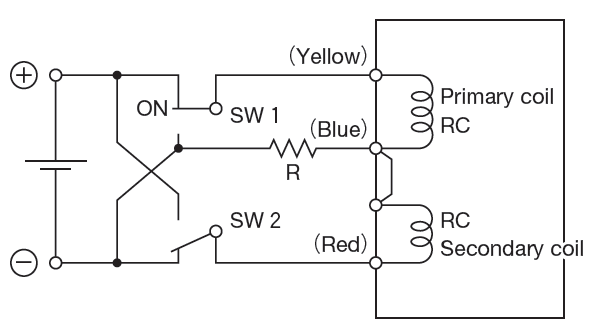
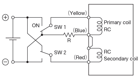
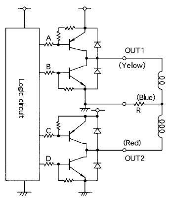
In either case, in order to cancel out the holding power of the permanent magnet on both coils (not just on the holding side), it is necessary to insert an external resistor ( R ) for degaussing. Thus, the unit operates on a two-loop structure. Thus, the unit operates on a two-loop structure.

Circuit example

Circuit example for TSB series (referential)

Various circuits for driving latching solenoids have been devised by their users. Following is an example for your reference.

Operational mode

operation mode matrix
circuit 3
× Modal Image
Scroll to Top